How To Add R-410 Refrigerant
Things Needed
-
R-410 refrigerant manifold gauge set
-
Adjustable wrench
-
Thermometer
Warning
Never use a manifold gauge set that has charged other refrigerants with an R-410 system.
An azeotrope refrigerant blends multiple refrigerant compounds to form a single refrigerant. Most refrigerant blends boil at different rates and require complete evacuation before adding a full charge. This is not the case with so R-410, which is considered a near-azeotrope, using compounds that boil at almost the same rate. Manufacturers include a refrigerant charge in new air conditioning systems that will provide the correct amount of refrigerant for the unit and a 15 to 25 foot refrigerant line set. Long line sets, the copper lines that the refrigerant travels through, will require additional R-410 refrigerant.
Step 1
Turn the air conditioning system off at the thermostat.
Step 2
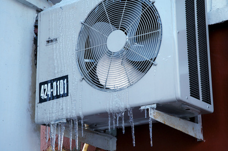
Check the identification tag on the outdoor condensing unit to verify the system uses R-410 as a refrigerant. Mixing R-410 with any other refrigerant will cause the compressor to seize.
Step 3
Connect the middle hose from an R-410 refrigeration manifold gauge set to a jug of R-410 (pink colored). Most hoses use screw-on fittings, but some use low-loss fittings that snap into place.
Step 4
Open the R-410 jug's valve by turning the handle clockwise.
Step 5
Remove the caps from both service valves, found where the refrigerant lines enter the condenser. Use an adjustable wrench to loosen them, if needed. The liquid refrigerant service valve connects to the small copper refrigerant line. The large refrigeration line, called the suction line, holds the vapor refrigerant as it returns to the condenser.
Step 6
Open the manifold's right-hand handle for one second then close the handle. This will purge the air and moisture from the manifold and the high-pressure hose. The handle opens when turned clockwise.
Step 7
Connect the hose on the manifold's right-hand side, high-pressure side, to the liquid refrigerant's service valve port. Screw-on fittings will screw onto the port, whereas low-loss fittings will snap into place.
Step 8
Purge the low-pressure, left-hand side hose for one second.
Step 9
Connect the manifold's low-pressure hose, left-hand side, to the suction-line service valve's port. Screw-on fittings will screw onto the port, and low-loss fittings will snap into place.
Step 10
Turn the air conditioner on at the thermostat. Allow the system to run for 10 minutes.
Step 11
Measure the temperature of the liquid refrigerant line 6 inches from the service valve with a thermometer. Write down this measurement.
Step 12
Check the high-pressure gauge, right-hand side, on the R-410 manifold set. The gauge will have a pressure reading in pounds per square inch gauge (PSIG) and a R-410 refrigerant saturation temperature measured in degrees Fahrenheit (F).
Step 13
Subtract the PSIG reading from the F reading. The resulting number will equal the subcooling value.
Step 14
Check the condenser's label for the designed subcooling value. If the calculated subcooling value reads less than the stated subcooling valve, then add R-410 to the system. Do not overcharge the system. Technicians often allow +/- 3 degrees for measurement error.
Step 15
Flip the R-410 refrigerant jug over. Always charge R-410, as a liquid, with the valve and hose facing the ground. Vapor charging will separate the refrigerant blend.
Step 16
Throttle the low-pressure, left-hand side manifold valve for 60 seconds. Throttling, i.e., opening and closing the valve every five seconds, will deliver a fully mixed refrigerant blend in liquid form without flooding the compressor.
Step 17
Allow the system pressures to equalize. When the gauge's needles have stopped dropping, the system pressures have equalized. This can take up to two minutes.
Step 18
Calculate the new subcooling value and compare it to the designed subcooling value as stated on the condenser's label. Add R-410 refrigerant as needed.
Step 19
Close the manifold and R-410 jug's valve handles. Disconnect the hoses and reinstall the caps on the service valve's ports.
