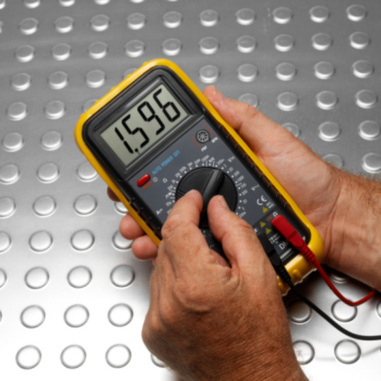
How To Test A Well Pump Control Box
Things Needed
-
Screwdriver set
-
Needle-nose pliers
-
Multimeter
Technicians should test a well pump's control box before pulling a nonworking pump from the well. When the water tank's pressure switch detects low water pressure, its switch closes, which turns on the electricity to the control box. Once the water pressure reaches the switch's high-pressure limit the switch opens, turning off the electricity. Well pumps with control boxes have start and run circuits. During start-up, the control box sends electricity to the pump motor through the start circuit. Once the pump motor reaches operational speed, the control box switches the electrical feed to the run circuit.
Step 1
Turn off the well's circuit breaker. The correct circuit breaker has a "Well" label.
Step 2
Open the control box's lid. The control box mounts to a wall next to the well's water storage tank. A wire set from the storage tank's pressure switch and a wire set that leads to the pump motor enters the control box.
Step 3
Inspect the control box's wiring diagram located on the back of the lid. The wiring diagram identifies the electrical terminals and lists their functions. The wires from the pressure switch connect to the electrical input terminals, usually called "L1" and "L2." The wires heading to the well's pump motor connect to terminals with a start, run and neutral function. These are usually labeled "S," "R" and "N." The wires connected to the green screw ground the well system. The chart next to the wiring diagram gives the well pump's operating voltage.
Step 4
Visually inspect the control panel's wires, wire connections, relay and capacitor. Replace all burnt or broken wires or parts. Tighten all wire connections with the correct screwdriver, often a flat-head screwdriver. Replace the capacitor if it has a leaking or swollen case.
Step 5
Pull the wire connectors off of the capacitor with needle-nose pliers. Lay a screwdriver across the capacitor's terminal. This discharges the capacitor. Turn a multimeter to the "Ohm" setting. Touch the multimeter's probes on the capacitor's terminals and watch the meter's reading. The meter should reach infinite, fall back slightly, then reach infinite again. If it does not, then replace the capacitor. Replace the wire connectors after testing the control box's capacitor.
Step 6
Turn on the circuit breaker. Turn a multimeter to its "VAC" setting.
Step 7
Open a faucet. This lowers the water pressure in the well's storage tank, which causes the well's pressure switch to turn on.
Step 8
Place the multimeter's probes on the control panel's "L1" and "L2" terminal. The voltage should read within 10 percent of the control panel's stated operating voltage. If not, then check the circuit breaker and the pressure switch.
Step 9
Place one multimeter probe on the control box's neutral terminal. Touch the other probe against the start terminal and take the multimeter reading. Once the control box's relay switches to the run phase, move the probe from the start terminal to the run terminal and take a reading. The voltage between the start and neutral terminals will drop to zero when the relay switches to the run phase. Compare these readings to the control box's operational-voltage ratings. If both ratings are within tolerance, then troubleshoot the well pump's motor. If the control box does not switch from start to run, then replace the relay.
