How To Check A Step-Down Transformer
A step-down transformer is one that converts high-voltage, low-current AC power to low-voltage, high-current power. Every home connected to the power grid gets its power from a step-down transformer on the power line. It reduces the transmission voltage from thousands of volts to the standard residential voltage of 240 volts, which is divided into two 120-volt legs at the main panel. Many electronic devices, such as phone chargers and laptops, employ step-down transformers in their power plugs to convert 120-volt electricity to a much lower voltage. In addition, home heating systems with thermostats and doorbells have step-down transformers. If you travel to a country with 240-volt power at the outlets, you need a step-down transformer to operate your 120-volt appliances.
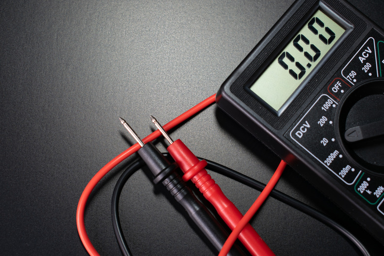
It's rare for transformers to malfunction, but they can overheat when supplying power on a continuous basis for an extended period of time. One of the transformer connections might melt, or a break may develop in one of the wires. You can test any transformer, including a phone charger transformer, using a multimeter. In output transformer testing, you use the voltmeter setting to check the output voltage while the transformer is connected to power. In a transformer continuity test, you disconnect the transformer from power and check resistance in both the input and output coils using the ohmmeter function.
How a Step-Down Transformer Works
How a Step-Down Transformer Works
A transformer is an electric induction device, and it only works with alternating current. It consists of a primary and secondary coil. Each coil may be wrapped around its own metallic core, or the coils may both be wrapped around the same core. The transformer works the same either way.
AC power supplied to the input coil induces a magnetic field in the core which in turn induces a current in the secondary coil. The ratio of the voltage in the primary coil to that in the secondary coil is directly proportional to the number of coil windings. In a step-down transformer, the input coil has more turns than the output coil, so the output voltage is lower than the input voltage.
Output Transformer Testing with a Voltmeter
Output Transformer Testing with a Voltmeter
Before you can test the output voltage on a transformer, you have to uncover the terminals of the output coil, and the transformer must be connected to power. To ensure an accurate reading, check the input voltage with your multimeter. Set the dial to read AC voltage in the appropriate range (usually 200 VAC) and touch the leads to the input terminals. If the transformer plugs into an outlet, simply insert the leads into the outlet slots. In a household circuit, you should get a reading close to 125 VAC.
Now, lower the voltage range and touch the voltmeter leads to the output terminals. If the transformer is installed somewhere, such as in your heating system's control panel, the output terminals are the ones that connect to the leads to go to whatever is being powered. There's no need to disconnect these leads. Just touch the meter probes to the terminals and note the meter reading. It should be close to the expected output.
Transformer Continuity Test
Transformer Continuity Test
A continuity test tells you whether there's a break in either of the coil wires. To conduct this test, the transformer must be completely disconnected, and you need to set the multimeter to read resistance in ohms (Ω). Touch the meter leads to the two input terminals of the primary coil (they may be marked H1 and H2) and check the reading. A very high or infinite resistance reading indicates a break in the circuit. If you're using a DMM, infinite resistance is denoted by OL (open line) on the screen. Perform the same test on the output leads (which may be marked X1 and X2). If either coil registers infinite resistance or OL, the transformer needs to be replaced.
