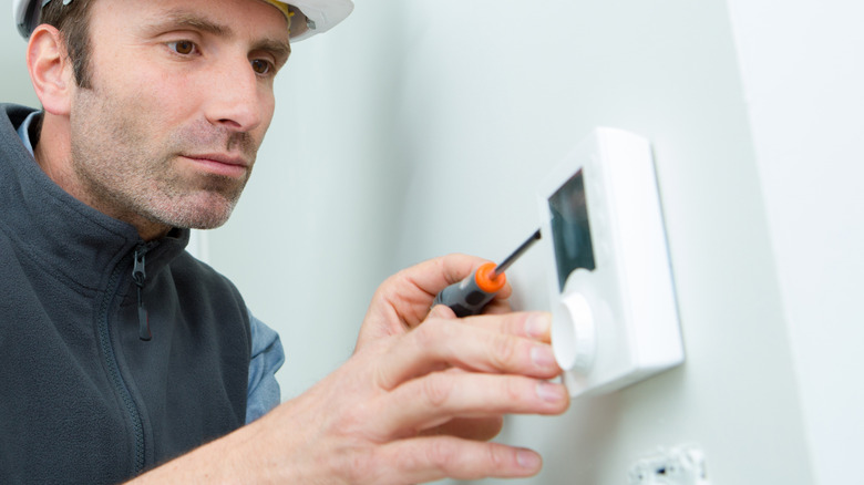
Instructions For Wiring A Trane Thermostat
There are a number of choices of Trane thermostats, depending on if it is a single heating and cooling source, such as a furnace and air conditioner, or an electric resistive heat system with an air conditioner. On the other hand, you might have a dual system, such as a heat pump with electric resistive elements, or gas for a backup. There are manual thermostats as well as programmable thermostats.
When performing service on the unit, check the filter and cooling coil to make sure there is no restriction to the airflow. Also, visually check all wires. Make sure they are tight and show no sign of getting hot.
Warning
As always, turn the breaker off and tag it before working on any electrical unit to avoid the breaker inadvertently being turned on while you are working on the unit.
Step 1
Choose your thermostat according to your needs. If there are a number of members in the house that come and go at different times, a manual Trane thermostat is probably the right choice. If there are regular periods of time that no one is home, it might save cost on energy to go with a Trane programmable thermostat.
Step 2
Connect the thermostat wires. If changing out a Trane thermostat, just mark the wires and replace them where they came off. If installing a thermostat from the beginning, the wires are normally color coded. The red wire is the power wire coming from the secondary winding of the transformer. It gets connected to the R terminal on the transformer. The yellow wire is connected to the coil on the cooling contactor, and the other end is connected to the Y terminal on the thermostat. The white wire is connected to the relay for the electric heat, or the gas valve. The green wire is connected to the fan relay and connected to the G terminal on the Trane thermostat. If it's a programmable thermostat and requires a common wire, this is usually the black wire and is connected to the common side of the secondary winding of the transformer–and, on the thermostat, it is connected to the C terminal.
Step 3
Connect the wires just as you connected them in the above step, except there is an orange wire that goes to the reversing valve. This energizes the reversing valve. This will put the heat pump in the primary heat source. The white wire is hooked to the heat relay to bring on the auxiliary or emergency heat. The auxiliary heat will come on automatically, depending on need. There is a switch on the thermostat for the emergency heat in case the heat pump fails.
Step 4
Turn the breaker on and test the unit. Be sure to test it in both the cooling and heating modes.
